- ▶0603i/10uF/6.3V/X7T (CL10Z106MQ9VPNC)

Abstract
Vehicles equipped with ADAS need to recognize the surrounding environment through various sensors and cameras, thus enabling them to respond accordingly. In order for a vehicle moving at high speed to recognize and process objects instantaneously, a processor for High Performance Computing (HPC) must be used. For MLCCs used in automobiles with this purpose, the proportion of small and high-capacitance products (4V - 6.3V MLCC for processors) is rapidly increasing in alignment with PCs and servers.
Samsung Electro-Mechanics supplies a number of ultrahigh-capacitance MLCCs that meet AEC-Q200 such as 0603i(1608m)/10uF and 0805i(2012m)/22uF at 125℃ for automotive electrics.
High Performance Computing in Automotive
The traditional mindset of MLCCs for automobiles are specs with high reliability, low capacitance, large size, or high voltage. This is because automotive MLCCs have been historically used for battery or voltage conversion, since high-performance processors that require quick operation are not used. However, as ADAS recently expanded beyond simple driver assistance to adopt partial automation, a vehicle must be equipped with a high-performance processor that can process a large amount of sensors or image data in real time and make driving decisions.
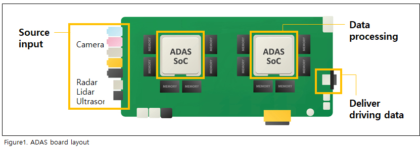
ADAS board configuration is generally simple: get data → decide → transmit driving data. Data collected through cameras, radar, and lidar are identified as people, objects, or vehicles in ADAS SoC(System on Chip). After the driving that befits the situation is decided, the determined data is transmitted to the powertrain. Here, a high clock speed and more cores are required because ADAS SoC must analyze a large amount of high-resolution image data in a short time to make driving decisions. This leads to increased power consumption, requiring more MLCCs. This trend is in line with the current development of PC and Server, so HPC's MLCC trend analysis is important to predict the future of MLCC for automotive electronics.
CPU for High performance computing in Automotive
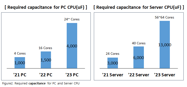
As a CPU gets more cores and adds various functions, the capacitance of MLCC as required by the CPU of a PC or server is also significantly increasing. In particular, as high-performance GPUs and various AI functions are integrated into CPUs, the required capacitance for MLCCs is rapidly increasing every year.
How to put more MLCCs in a limited space
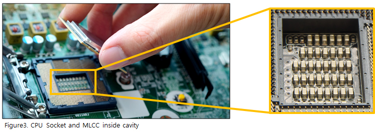
While the required capacitance of MLCCs keeps increasing, the area where MLCCs can be placed is limited. As CPU performance increases, CPU performance becomes more sensitive to external noise, and the farther the MLCC is from the CPU, the greater the noise. For this reason, CPUs that use socket type such as a desktop or server place MLCCs by drilling cavities in the socket.
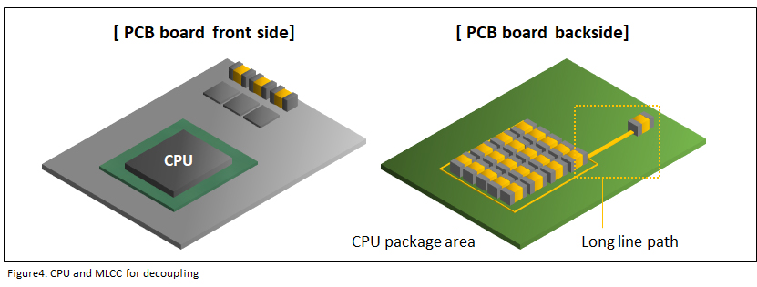
If the MLCC is soldered to a PCB without using the socket type due to restrictions such as thickness or there is no need to replace the CPU, the MLCC is placed on the right back of the board where the CPU is surface-mounted to keep it as close to the CPU as possible. However, the area available for an MLCC to be surface-mounted is limited.
Currently, the average MLCC capacitance as required by ADAS SoC is about 2,000uF, but judging from the HPC cases discussed above, the capacitance is expected to more than double within one or two years. This means twice as many MLCCs will be needed, and it is surprisingly easy to put more MLCCs in a limited space by adopting a smaller size.
For convenience of calculation, we will simply simulate focusing only on the chip size without considering the surface-mount spacing for parts.
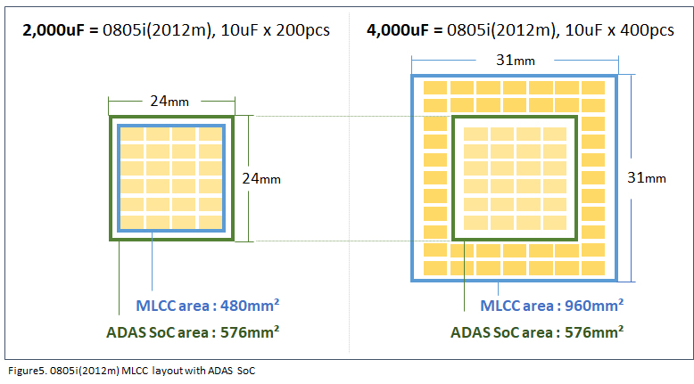
Currently, a typical ADAS SoC has an area of 576mm² (24x24mm). If two hundred 0805i (2012m), 10uF units are placed to realize 2,000uF, the MLCC footprint is 480mm², allowing MLCC placement comfortably within the ADAS SoC package area.
However, assuming that up to 4,000uF will be required in accordance with the HPC trend due to the high specification of ADAS SoC in the future, the MLCC must be placed quite far from ADAS SoC if the same 0805i (2012m) and 10uF products are used.
Samsung‘s small, ultrahigh-capacitance Automotive MLCC
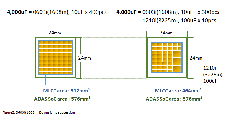
In order to solve this problem, Samsung Electro-Mechanics has developed 0603i (1608m), 10uF, 6.3V that supports AEC-Q200 and can realize high capacitance in a smaller size. By using four hundred 0603i, 10uF, 6.3V units smaller than 0805i (2012m) to realize 4,000uF, you can get a total MLCC area of 512mm², which makes it possible to place the MLCCs close to the ADAS SoC without problems. Furthermore, by using also 1210i (3225m) and 100uF products that are now in mass production, customer can implement the composition in an even smaller space.
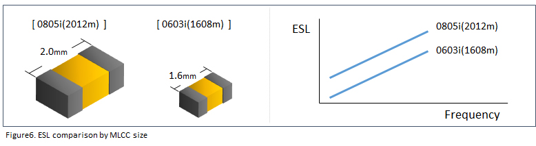
Additionally, if the small size is used, the internal path gets shorter to improve ESL.
Samsung Electro-Mechanics is also mass-producing 0805i (2012m), 22uF, 6.3V and 1206i (3216m), 47uF, 4V products. Depending on your functional requirements, Samsung Electro-Mechanics has a variety of products to support your technical needs.
| Samsung |
Size (mm) |
Cap (Voltage) |
Temp. |
Data Sheet |
| CL10Z106MQ9VPNC |
0603i (1608m) |
10uF (6.3V) |
X7T (125℃) |
 |
| CL21Z226MQYVPNE |
0805i (2012m) |
22uF (6.3V) |
X7T (125℃) |
|
| CL31Z476MRKVPNE |
1206i (3216m) |
47uF (4V) |
X7T (125℃) |
|
If you need more information, including samples, please click here to submit an inquiry.