go to the gnb menu go to the content

FAQ

  • MLCC (Class II) product has the characteristic that capacitance is decreased when DC voltage is applied, This could be measured using the typical LCR meter. 


    - Measurement equipment : LCR meter E4980A + Test Fixture 16034G/E (Keysight Technologies Corp.)
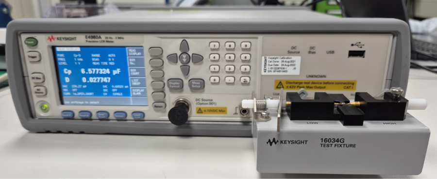


    - Test conditions

    1) Frequency : refer to SPEC sheet for each product (e.g., 1kHz, 120Hz)

    2) AC voltage: refer to SPEC sheet for each product (e.g., 1Vrms, 0.5Vrms)

    3) DC voltage : from 0Vdc to Rated voltage, keep time(60sec) by each point

    4) ambient temperature  : 25℃ ± 3 ℃


    ※ Caution

    1) Measurement should be proceeded after ‘pre-treatment at 150℃ for 1hour and keep at room temperature for 24hour’

      *refer to FAQ “MLCC Aging phenomenon”


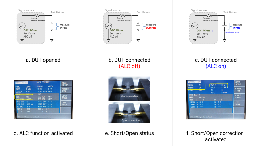
    2) Because the voltage source of LCR meter has internal resistor, the voltage between DUT terminals may differ from setting voltage. This equipment(E4980A) provides ALC(Auto level control) function to control DUT voltage. Therefore, capacitance should be measured while ALC function is activated. If ALC function is not activated, the capacitance value may be a little low. (Figure a, b, c, d)


    3) Since parasitic of the  test fixture can affect on capacitance value, Short status and Open status of fixture and cable length must be properly corrected. (figure e, f)


    Please refer to the user guide of the equipment for detailed measurement setting methods.


    [Reference]

    - Impedance Measurement Handbook, Keysight Technologies Corp. 6th Edition, 2020

  • There is no specification for allowable current of MLCC.
    When DC voltage is applied into MLCC, there is no issue since almost no current flows through the MLCC, however, when the AC voltage or pulse voltage is applied, the current flows through the electrode which leads to generate heat. Therefore, check the self-heating temperature by input AC or pulse voltage when the capacitor is used.


    2-6. Self-heating Temperature ( in Datasheet)
    It is necessary to design the system, with considering self-heating generated by the ESR (Equivalent Series Resistance) of MLCC when AC voltage or pulse voltage is applied to MLCC.
    2-6-1. When MLCC is used in an AC voltage or pulse voltage circuit, self-heating is generated when AC or pulse current flows through MLCC. Short-circuit may be occurred by the degradation of MLCC’s insulating properties.
    2-6-2. The reliability of MLCC may be affected by MLCC being used in an AC voltage or pulse voltage circuit, even the AC voltage or the pulse voltage is within the range of rated voltage.
      Therefore, make sure to check the following conditions.
    1) The surface temperature of MLCC must stay within the maximum operating temperature after AC or Pulse voltage is applied.
    2) The rise in increase by self-heating of MLCC must not exceed 20℃


  • The MLCC product is grouped based on temperature characteristics, and the temperate ranges for X5R is -55~85˚C and X7R is -55~125˚C. This does not mean that the MLCC can operate in the relevant temperature but indicates that the change to capacitance value in the temperature range is within ±15% or ±22%. As a result, should you continue to use the MLCC at the maximum temperature of the temperature range, the lifespan of the product may drastically decreased.
  • MLCC types can be classified Class1 (thermometer) and Class2 (high dielectric system).
    Class 1 type uses titanium oxide as a dielectric material, and capacitance value changes according to temperature or voltage in ppm units. The attainable capacity standard is nF units or less, and is generally used for impedance matching.
    Class2 uses a dielectric called Barium Titanate, attains μF-level capacity, and is generally used for decoupling, and the capacity change with regards to temperature change or voltage approval is relatively large.


  • Temperature characteristics with regards to MLCC capacitance shows how much capacitance value changes within the MLCC’s temperature range. Within the temperature range, should capacitance change be small, it can be said that the temperature characteristic is excellent.

  • Samsung Electro-Mechanics indicates the MLCC storage conditions in the product spec sheet as shown below, This is to maintain the durability of the packaging material and prevent oxidation of the plating surface of the product.


    ※ Details of set storage condition within the spec
    6-1-1. Recommendation for temperature/humidity
    Even taping and packaging materials are designed to endure a long-term storage, they should be stored with a temperature of 0~40°C and an RH of 0~70% otherwise, too high temperatures or humidity may deteriorate the quality of the product rapidly.


    As oxidization is accelerated when relative humidity is above 70%RH, the lower the humidity is, the better the solderability is.

    As the temperature difference may cause dew condensation during the storage of the product, it is a must to maintain a temperature control environment.


    6-1-2. Shelf Life
    An allowable storage period should be within 6 months from the outgoing date of delivery in consideration of solderability. As for products in storage over 6 months, please check solderability before use. 

  • Do you want to check the DC bias features (valid capacitance) of a product?


    If you are curious about the DC bias features (valid capacitance), S-parameters (frequency features) based on DC voltage and temperature, or other features, please use the component library.


    The component library provides a “simulation” on electrical properties of passive components necessary for product development by researchers of application manufacturers.


    One can select the appropriate passive component without testing on a real product.


    Component Library >>


    You can check dc bias data of CL10A475KL8NRN model in our component library.


    1) Pleas enter 'CL10A475KL8NRN' in black [Part Number]

    2) Double-click the row of the model you want to select.

    3) Click the 'DC Bias' button in 'Graph Type' menu on the left.

    4) DC Bias graph is created in the new window and data can be checked or downloaded.


    We are introducing how to use the component library through video.


    Tutorial Video >> 

  • The lifetime of MLCCs is affected by temperature condition and the applied DC voltage condition, It can be expressed by the following acceleration equation.


    For example, the endurance test performed under 85ºC, 16V environment is an accelerated test equivalent to 2,374.16 times under 65ºC, 4V environment. MTTF (40pcs of test sample, 60% confidence level by MIL-STD-690, JIS C 5003) is 103,562,200h, FIT is estimated to be 9.656.

    Voltage acceleration factor (‘n’) and Temperature acceleration factor (‘Ea’) used in the equation differ by the type and structure of the ceramic material.


  • - Isat saturation current

    : When the DC current is applied to the inductor, the permeability of the material decreases, resulting in the decrease in inductance. Here, the DC current value at which inductance decreases by 30% compared to its default value (or nominal value) is called the Isat. Should the last value be too low, the effective inductance at the DC current is low, which may have an impact on the circuit’s operation, and therefore, it is important to select an inductor by taking into consideration the Isat margin.


    - Itemp temperature characteristics

    : When DC current is applied to the inductor, because of the coil’s resistance, that is, DCR, the heat and temperature of the inductor increases. Here, Itemp is the DC current value at which the temperature of the inductor increases by 40 ℃ compared to the initial value (DC 0A). If the Itemp value is too low, the component temperature of the DC current is high, and therefore, you must select the inductor taking into consideration the Itemp margin.

  • Tape or packaging materials are designed to withstand long-term storage, but it must be stored in temperature of 0~40°C and RH 0~70%. Due to excessively high temperature or humidity, product quality may drastically decrease.
    Should the relative humidity be 80% RH or higher, oxidation is accelerated, and solderability is improved as humidity decreases. Condensation may occur due to temperature differences during product storage, and therefore, you must be cautious of temperature control. 

For more information, please submit a customer inquiry, and our C/S representative will get back to you.

Inquiry
Online PR Hall Subscribe to Newsletter Latest Articles