| Characteristics of MLCC |
|---|
|
Copyright. SAMSUNG ELECTRO-MECHANICS All rights reserved.
SAMSUNG Characteristics of MLCC [1] Basic [2] IR, BDV, [3] TCC, Aging [4] DC-Bias, AC Voltage, IZI
SAMSUNG
Characteristics of MLCC, Basic
MLCC Structure and Capacitance Design
-Capacitance: Proportional to an internal electrode(A) area, Inversely proportional to distance between internal electrodes(t)
왼쪽 그림 - Ctotal=C1+C2+C3+C4+C5, Inner Electrode(Ni), Dielectric, External Termination(Cu-Ni-Sn), Inner Electrode(Ni), Dielectric
오른쪽 그림 - Ctotal=ε0εr(n-1)A/t, ε0: Vacuum Permittivity(8.854X10⁻¹²F/m), εr: Dielectric Constant, t: Thickness, A: Active area, n: Layer number, Dielectric, Internal Electrode, Active Area ↑, Dielectric, Internal Electrode, Distance ↓
SAMSUNG
Characteristics of MLCC, Basic
The electrical characteristics of MLCC
- The MLCC characteristics changed according to the environment and conditions of use
List - Temperature (TCC), Description - Capacitance change in operating temperature range → Design considering Deivce/Circuit usage temperature
List - DC-bias, AC Voltage, Description - Capacitance change by applied DC-Bias & AC Voltage
List - Aging, Description - Reduced capacitance over time
List - Rated Voltage, Description - Maximum applicable voltage
List - Insulation Resistance (IR), Description - Leakage current flow through MLCC
List - Dissipation Factor (DF), Description - Energy Loss in MLCC (=ESR/Reactance)
List - Breakdown Voltage (BDV), Description - Insulation breakdown by an applied voltage rise
List - Ripple current, Description - Rise in surface temperature by ripple current
List - Impedence (Z) & ESR, Description - Change in Impedance and ESR by frequency change
SAMSUNG
Characteristics of MLCC, Basic
The effect of electrical characteristics of MLCC on ECU
- Ac voltage ripple, efficiency and reliability of the ECU represent MLCC electrical characteristics
List - TCC, DC_Bias, AC Voltage, Aging / MLCC - Control Factor - Capacitance (C) / MLCC - Effect - Impedance (Z), C 10% ↓ → Z 10% ↑ / Vehicle ECU - Control Factor - AC Voltage Ripple (V AC), Z 10% ↑ → V AC 10% ↑ (V AC=I AC x Z) / Vehicle ECU - Effect - A significant increase in ac voltage can cause malfunction
List - ESR / MLCC - Control Factor - ESR at SRF / MLCC - Effect - Impedance (Z), C 10% ↓ → Z 10% ↑ / Vehicle ECU - Control Factor - AC Voltage Ripple (V AC), Z 10% ↑ → V AC 10% ↑ (V AC=I AC x Z) / Vehicle ECU - Effect - A significant increase in ac voltage can cause malfunction
List - ESR/DF / MLCC - Control Factor - Below SRF / MLCC - Effect - Thermal (Power Loss) / Vehicle ECU - Control Factor - Efficiency / Vehicle ECU - Effect - If the standard specifications are met, few malfunction will occur on ECU
List - IR / MLCC - Control Factor - Insulation / MLCC - Effect - Leakage Current / Vehicle ECU - Control Factor - Efficiency / Vehicle ECU - Effect - If the standard specifications are met, few malfunction will occur on ECU
List - BDV / MLCC - Control Factor - Voltage immunity / MLCC - Effect - ESD / Vehicle ECU - Control Factor - Reliability / Vehicle ECU - Effect - If the standard specifications are met, few malfunction will occur on ECU
SAMSUNG
Characteristics of MLCC, IR, BDV
IR and BDV characteristics of MLCC
IR and BDV are determined by dielectric material and MLCC structure
[IR] Spec. 10,000MΩ or 100MΩ÷C[㎌] Whichever is smaller
Test Condition, Rated Voltage, 25℃, 60~120 sec. charging less than 50mA
Ex) 10㎌, IR, ILk, 100MΩ÷10㎌ → 10MΩ, 5V/10MΩ → 0.1㎂ or less
[BDV] Test Condition Spec., 250% of rated voltage
Judgement No dielectric breakdown or mechanical breakdown
SAMSUNG
Characteristics of MLCC, TCC, Aging
Temperature and Aging characteristics of MLCC
- Capacitance of MLCC decreases in over time and high temperature operating conditions
※ Reduced capacitance by long-term storage will be recovered to original capacity when soldering
[TCC], [Aging]
X5R (%ΔC ±15%, Temperature Range -55~85℃)
X7R (±15%, -55~125℃), Y5V (=22/-82%, -30~85℃)
Ct=Capacitance value, t hours after the start of aging
C0=Initial capacitance value, k=Aging constant, t=Aging time
SAMSUNG
Characteristics of MLCC, DC-Bias, Ac Voltage
Voltage Bias characteristics of MLCC
- The effective capacitance of the MLCC is changed according to the applied voltage condition
[DC-Bias] An increase the applied DC Voltage to the MLCC
→ Dipoles to be aligned in the direction of the DC field
→ A decrease in the polarization change rate in the AC field
→ A decrease in capacitance
[AC Voltage] An increase the applied AC voltage to the MLCC
→ An increase the polarization change rate in the AC field
→ An increase capacitance
SAMSUNG
Characteristics of MLCC, IZI
Impedance(Z) characteristics of MLCC
- Output voltage ripple is proportional to impedance and inversely proportional to capacitance
Z=-j/2πf·C+ESR+j2πf·ESL
j/2πf = Xc, j2πf·ESL=Xesl
Impedance graph by the capacitance, Output voltage ripple by the capacitance
SAMSUNG
[Attachment]Characteristics of MLCC
Capacitance is generated by dipole that formed by spontaneous polarization
- Heat treatment (125℃ ↑) changes the tetragonal structure at 125℃ ↓ → Ti 4 + Spontaneous polarization(Dipole formation) occurs → dielectric constant increases (capacitance ↑)
[Cubic] Centered Ti4+ → No Dipole
[Tetragonal] Off-centered Ti4+, (+), (-) centers are changed as Ti4+ is biased to one side
→ Dipole formation (Spontaneous Polarization)
→ Permittivity ↑
Fig1. MLCC Grid Structure and Polarization phenomenon of BaTiO3
SAMSUNG
[Attachment] DC-Bias of MLCC
When DC voltage is applied to MLCC, capacitance is reduced
- DC voltage is applied to MLCC → Dipoles are aligned in the direction of the dc field → the polarization change rate decreases in the AC field → Capacitance decreases (permittivity ↓)
No dc bias, With a small dc bias, With a large dc bias
Fig2. Number of dipoles responding to ac-field decreases with increasing DC bias leading to lower capacitance loss
[Attachment] Aging of MLCC
The aging of MLCC(BaTiO3) is a process to relieve mechanical stress
Structure of BaTiO3 - Tetragonal: a=b"<"c, (="" treatment]="" heat="" [after="" -="" batio3="" of="" effect="" aging="" ↑="" permittivity="" →="" dipole="" center)="" @="" energy="" ti4+(unstable="" off-centered="">150℃), degree of freedom of dipole ↓, [After Aging], 90' dipole formation to relieve mechanical stress(c">"a), degree of freedom of dipole ↓, Cap. ↓
- Variation of capacitance by aging time
Copyright. SAMSUNG ELECTRO-MECHANICS All rights reserved. |
기술문서
이메일 무단수집거부
본 웹사이트는 게시된 이메일 주소가 전자우편 수집 프로그램이나 그 밖의 기술적 장치를 이용하여 무단 수집되는 것을 거부합니다. 이를 위반 시 『정보통신망 이용촉진 및 정보보호 등에 관한 법률』등에 의해 처벌 받을 수 있습니다.
아이디어 제안에 대한 정책
삼성전기 및 삼성전기 임직원은 당사가 공식적으로 요청하지 않았음에도 불구하고
여러분께서 일방적으로 당사에 제출하는 아이디어나 제안 등을 수령하거나 검토하지 않습니다.
이는 제출하신 내용이 당사 내부적으로 개발한 제품, 기술, 서비스와 유사할 경우 발생할 수 있는
오해와 분쟁을 방지하고 나아가 여러분의 창의적인 아이디어를 적극 보호하기 위함입니다.
이러한 취지를 이해하여 주시고 구체화되지 않은 아이디어나 콘셉트(Concept) 단계의 제안이
당사에 제출되지 않도록 하여 주시기 바랍니다.

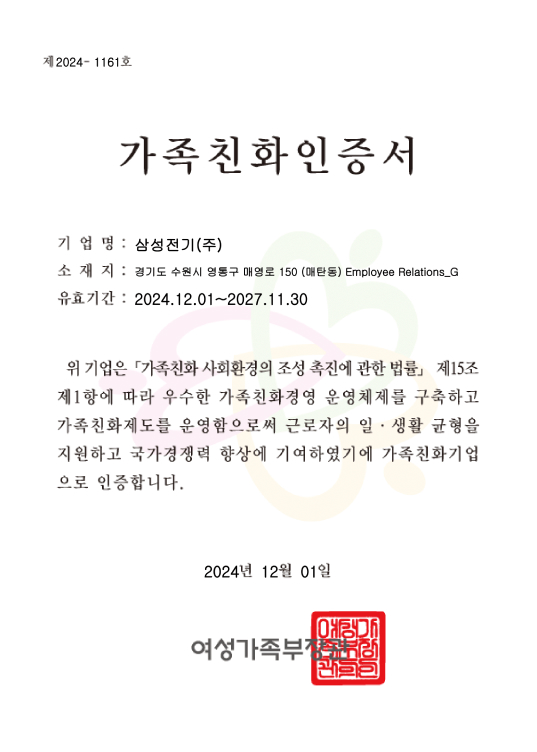
가족 친화 인증서
- 기업명:
- 삼성전기(주)
- 소재지:
- 경기도 수원시 영통구 매영로 150 (매탄동) Employee Relations_G
- 유효기간:
- 2024.12.01 ~ 2027.11.30
위 기업은 『가족친화 사회환경의 조성 촉진에 관한 법률』 제 15조 제 1항에 따라 우수한 가족친화경영 운영체제를 구축하고 가족친화제도를 운영함으로써 근로자의 일·생활 균형을 지원하고 국가경쟁력 향상에 기여하였기에 가족친화기업으로 인증합니다.
2024년 12월 01일여성 가족부 장관(인)

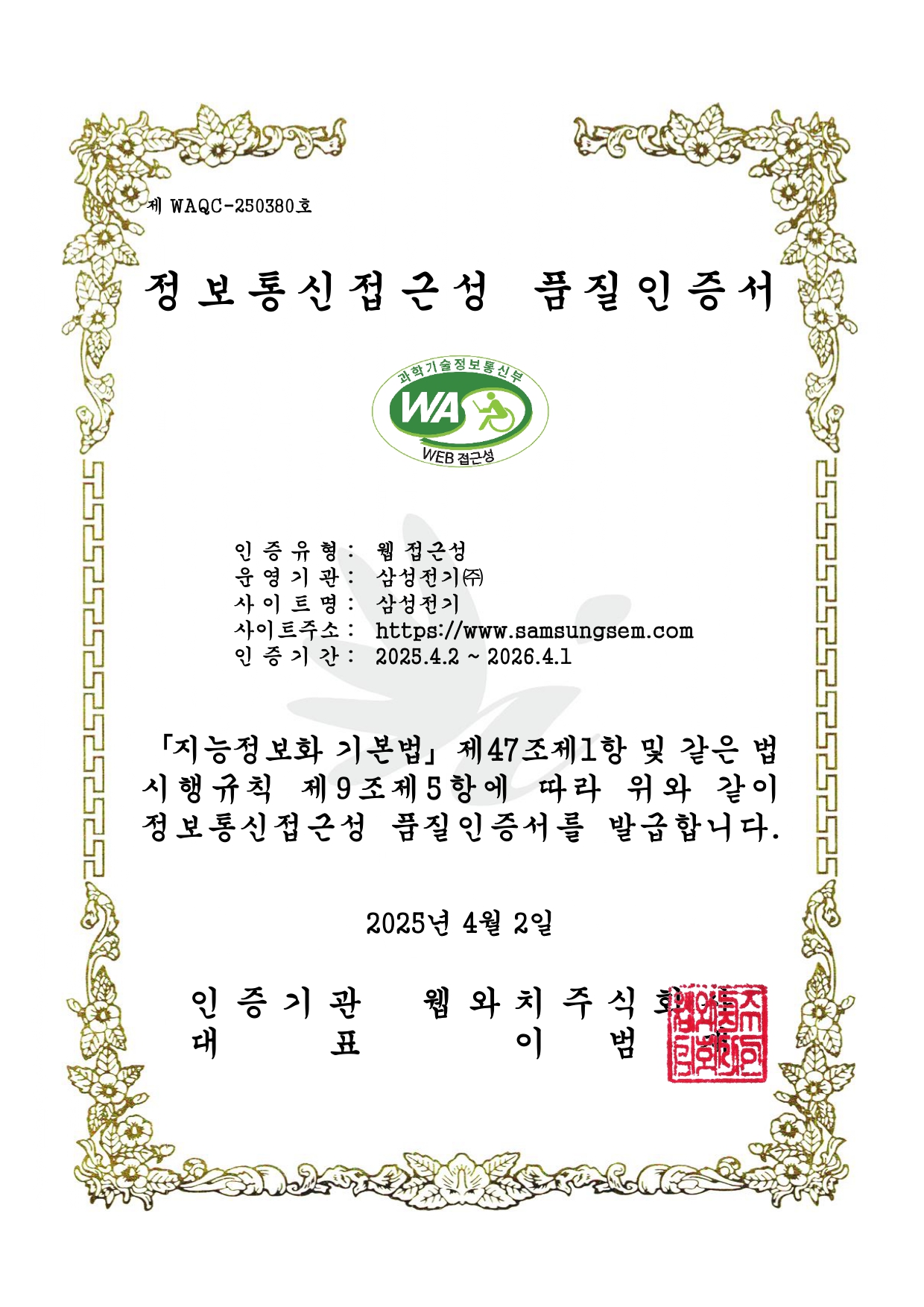
제WAQC-250380호 정보통신접근성 품질인증서
- 인증유형:
- 웹 접근성
- 운영기관:
- 삼성전기(주)
- 사이트명:
- 삼성전기
- 사이트 주소:
- https://www.samsungsem.com
- 인증기간
- 2025.4.2 ~ 2026.4.1
「지능정보화 기본법」 제47조제1항 및 같은 법 시행규칙 제9조제5항에 따라 위와 같이 정보통신접근성 품질인증서를 발급합니다.
2025년 4월 2일인증기관 대표, 웹와치주식회사 이범재
삼성전기의 최신뉴스를 만나보세요.
삼성전기가 그려나가는
새로운 미래와 혁신의 순간을 모아
신속하게 전달해 드립니다.
-
개인정보 수집 및 이용에 동의합니다. 내용보기
1. 개인정보 수집 목적
삼성전기(이하 "회사"라고 함)에서 발행하는 보고서 또는 뉴스를 전달하기 위해 메일정보를 수집하고 있으며, 수집된 개인정보는 정해진 목적 이외의 용도로는 이용되지 않으며 수집 목적이 변경될 경우 사전에 알리고 동의를 받을 예정입니다.
2. 개인정보의 보유 및 이용기간
뉴스레터 수신거부 신청 시 귀하의 개인정보를 지체 없이 파기합니다. 다른 법령에 따라 보존하여야 하는 경우에는 보유 및 이용기간이 경과한 개인정보를 파기하지 아니하고 보유할 수 있습니다.
3. 수집하는 개인정보의 항목
- 항목 : 이메일
- 보유기간 : 뉴스레터 수신거부 신청 시까지
- 보유목적 : 삼성전기 보고서 및 뉴스 제공
- 자동수집항목 : IP, 쿠키(Cookie), 접속 로그
4. 개인정보 처리의 위탁에 관한 사항
'뉴스레터 발송'은 서비스 이행을 위해 아래와 같이 외부 전문업체에 취급 위탁하여 운영하고 있습니다. 회사는 위탁계약 체결 시 개인정보보호법 등 관련 법령에 따라 위탁업무 수행목적 외 개인정보 처리금지, 기술적·관리적 보호조치, 재위탁 제한, 수탁자에 대한 관리·감독, 손해배상 등 책임에 관한 사항을 계약서 등 문서에 명시하고, 수탁자가 개인정보를 안전하게 처리하는지를 감독하고 있습니다. 회사는 위탁업무의 내용이나 수탁자가 변경될 경우에는 지체 없이 고지하겠습니다.
개인정보 처리의 위탁에 관한 사항 - 위탁업체명, 대표 전화번호, 위탁업무에 대한 내용을 제공합니다. 위탁업체명 ㈜더위버크리에이티브 대표 전화번호 02-517-5133 위탁업무 뉴스레터 발송, 홈페이지 운영 및 유지 관리 ※ 귀하께서는 귀하의 개인정보 수집·이용에 대한 동의를 거부하실 권리가 있으며, 동의를 거부하실 경우 뉴스레터를 받아보실 수 없습니다.
상기 내용을 읽고 개인정보 수집 및 이용에 동의합니다. (광고성 정보 수신 동의를 포함하고 있습니다.)
-
삼성전기 뉴스레터 수신에 동의합니다.

